
Cables with external actuation
With external actuation, the cables run uninterrupted from the shifter to the cable box on the hub — no separate cable stop is needed. Every SPEEDHUB has been made this way since late 2024, and every disc brake (DB) version always.
Rohloff cables
Section titled “Rohloff cables”- spiral housing (4.7 mm) with an integrated plastic liner,
- 1.1 mm stainless inner wire with a 4×5 mm barrel nipple — a standard size, available anywhere in the world,
- sealed end caps that keep water and dirt out.
They also come as a complete set: cable set (Art. no. 8268), or the longer tandem version (Art. no. 8267).
Do not crush the housing ends, and give every end an end cap — just pushed on, not crimped.
Routing on the frame
Section titled “Routing on the frame”The cables can run along the chainstay or the top tube. Either way, the 1 cable connects at the bottom of the cable box and at the front of the shifter; the 14 cable at the top of the box and at the back of the shifter. Route the housing free of tension, with generous curves. Set the axle plate position to suit: Axle plate position.
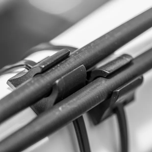
If the frame has no cable guides, the Rohloff Cable Manager Kit (Art. no. 5201) helps: a long cable tie (255 × 2.7 mm) holds the two clips to the frame, and two small ones (75 × 2.5 mm) hold the cables in them. Stick the foam pads under the clips first.
Connecting the cables
Section titled “Connecting the cables”-
Prepare the cable box. Open it, take out the cable pulley, the two cover screws and the two adjusters, close it again, fit the box to the shift housing and fix it with the knurled screw.
-
The housings. Route the housings from the shifter to the cable box, cut them to length — a clean, square cut — and put an end cap on both ends. Then take the cable box off again.
-
The wires. Thread the wires into the shifter (The twist shifter) and through the housings. The housings must sit fully home in the end caps and the shifter’s stops.
-
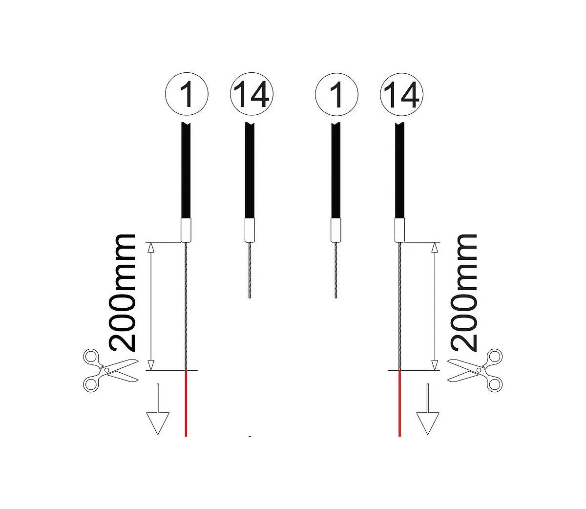
Cutting to length. At the cable box, pull the 1 cable fully out and cut it to 200 mm from the end of the housing, end cap included. Then pull the 14 cable fully out — the 1 cable retracts — and cut it to 200 mm too. The 200 mm brass tube (Art. no. 8712) makes this precise.
-
Direction check. Pull the 14 cable to the shifter’s stop: the grip turns past gear 1. Pull the 1 cable: it turns past 14. If it is the other way round, the cables are swapped.
-
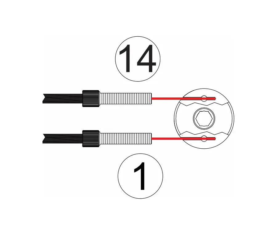
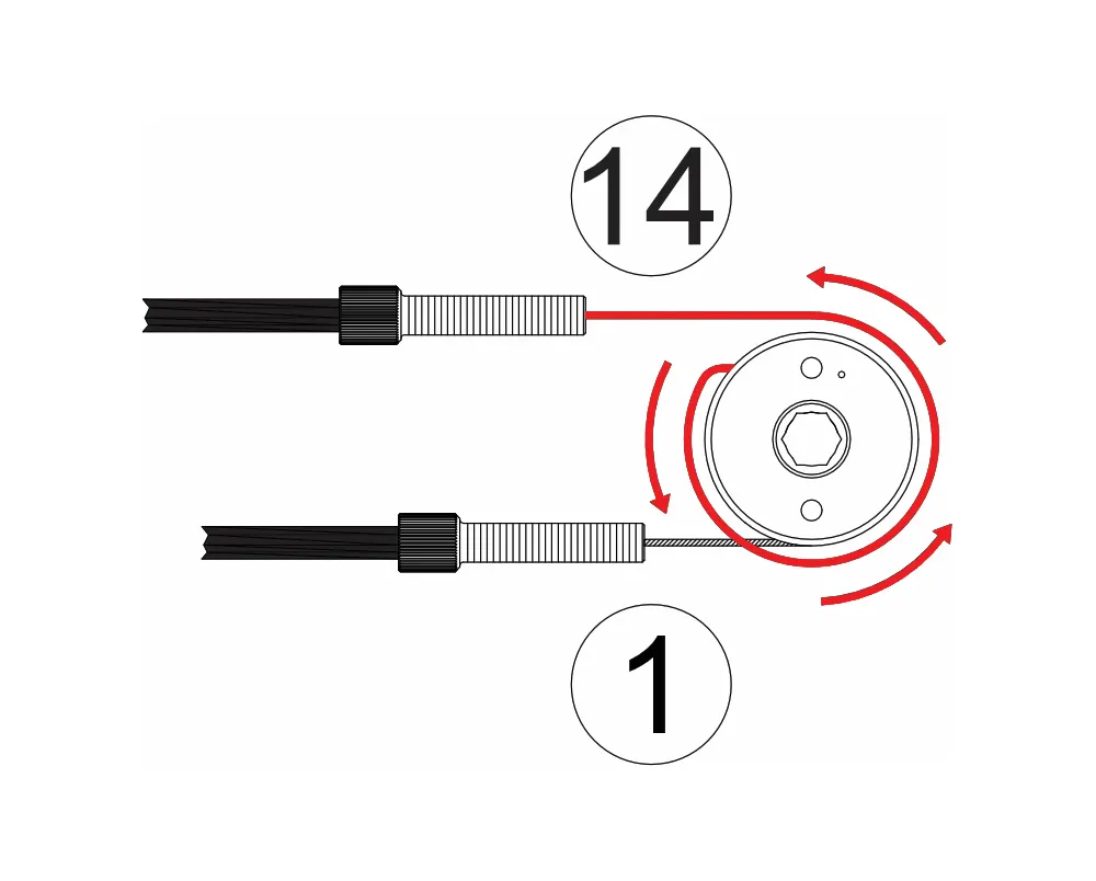
The pulley. Loosen the pulley’s two clamp screws about three turns (2 mm Allen). Slide the adjusters onto the cables, then push the 1 cable into hole 1 and the 14 cable into hole 14, to the stop. The pulley’s hex front faces up. Tighten the screws (M4×4, 2 mm, 1.5 Nm).
-
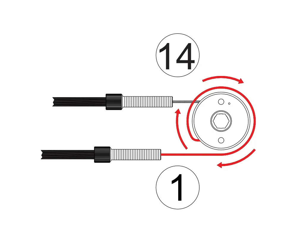
Lay the 1 cable in the pulley groove in a clockwise loop, the 14 cable in an anticlockwise loop. Both grooves must be completely filled, and the cables must not cross.
-
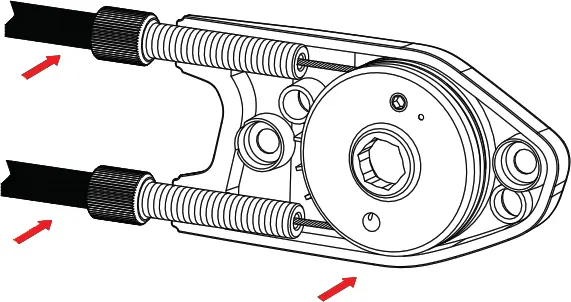
Put the pulley with its adjusters into the cable box. Turn the shifter from 1 to 14 and back to check that the pulley turns easily, in the same direction as the grip.
-
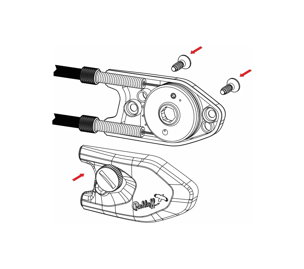
Fit the cover without trapping a cable, and tighten the two screws evenly. On the plastic cable box (KN6041 STS plus 4×12, TX20) 1 Nm, on the metal one (M4×10, TX20) 3 Nm — overtightening strips the plastic thread. Screw both adjusters fully in.
-
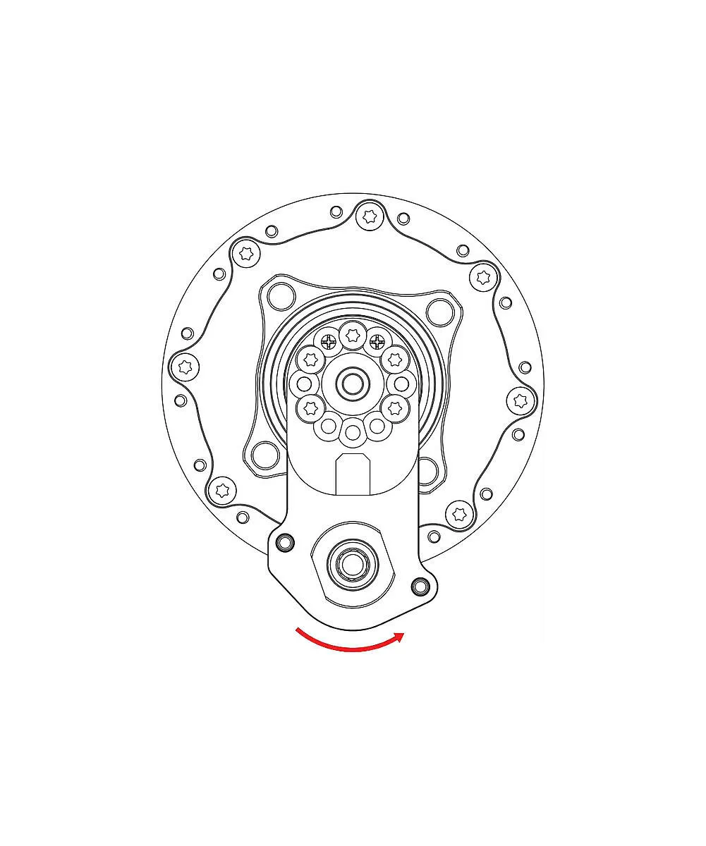
At the hub, turn the shift shaft’s hex anticlockwise to the stop with an 8 mm spanner — the gearbox is now in gear 14. Put a thin film of Vaseline on the pulley’s bearing bush.
-
Set the shifter to 14, push the cable box onto the guide pins — moving the grip slightly helps — and tighten the knurled screw by hand.
Tension and the gear mark
Section titled “Tension and the gear mark”Unscrewing the adjusters increases the tension, screwing them in reduces it. Set it so the grip has about 2 mm of free play. If the mark is not exactly opposite the numbers, screw one adjuster in and the other out by the same amount.
Finally check that all 14 gears work — 14 gears = 13 clicks. If not, the cable box went on out of gear 14: Fitting the rear wheel.
Frequently asked questions
- How long should the cables be cut at the cable box?
- Both to 200 mm, measured from the end of the housing including the end cap: first the 1 cable pulled fully out, then the 14. The 200 mm brass tube (Art. no. 8712) is the most accurate aid.