
Fitting an A12 for the first time
An A12 does not come off the shelf: the bushings and spacers are chosen or made from a measurement of your frame, separately for the left and right dropouts. This page shows what happens at the measurement and the first fitting — for later removal and refitting see Removing and fitting an A12 wheel; for the overview, The A12 system.
1. Axle plate and torque support
Section titled “1. Axle plate and torque support”First the sample axle plate with the sample support is held in its final position against the inside of the left dropout. The plate must sit flat in a 40 mm circle around the axle, and its support section must either clear the frame or sit flat too. If a weld or a reinforcement lifts it even slightly, hub and disc would sit crooked — that frame cannot take an A12.
| Width | Brake mount on the frame | Axle plate | Support |
|---|---|---|---|
| 142, 148, 177 mm | IS2000, IS caliper | A12 OEM2 (8559) | SPEEDBONE (8550) |
| 142, 148, 177 mm | IS2000, post-mount caliper | A12 OEM2 (8559) | Monkey Bone 160 (8553) or 180 (8554) |
| 142, 148, 177 mm | post mount | A12 PM (8558) | PM Bone (8555) — with a disc one size up |
| 197 mm | IS2000, post-mount caliper | A12 OEM2 197 (8562) | Monkey Bone-10 160 (8553-10) or 180 (8554-10) |
| 197 mm | post mount, built for 160 mm | A12 OEM2 197 (8562) | Fat Bone 180 (8556) — with a 180 mm disc |
| 197 mm | post mount, built for 180 mm | A12 OEM2 197 (8562) | Fat Bone 203 (8557) — with a 203 mm disc |
An A12 comes with a chain tensioner. With a belt, Gates’s rules apply too — see Gates belt drive.
2. Measuring the dropouts
Section titled “2. Measuring the dropouts”Supported dropouts: DT/Maxle, Syntace X-12 V1 and V2, 12 mm thru-axle systems with spacer rings, frames with a UDH (universal derailleur hanger), Paragon Machine Works PA/PB 454/453 and DR/B 4056/4055 dropouts, and free combinations of these. Paragon dropouts take no snubber, so they cannot be used with a Gates belt.
The measurement uses two methods, on both sides:
- Check bushings and the 0.5/1.0 mm frame gauge. The gauge’s 0.5 mm side shows whether the dropout is too narrow, the 1.0 mm side whether it is too wide. Where needed, 0.5 mm shims or an over-long check bushing are added — the number of shims goes onto the order.
- Calipers, with a measuring cylinder and screw: the combined thickness of cylinder, dropout and screw decides whether an A12 fits.
| Dropout | Fits if the caliper reading is |
|---|---|
| DT/Maxle, spacer-ring system, UDH | 47–57.5 mm |
| Syntace X-12 V1 | 51–57.5 mm on both sides |
| Syntace X-12 V2 | 51–57.5 mm on the disc side, 47–57.5 mm on the sprocket side |
With a UDH, the sprocket side needs no measuring: the Rohloff UDH stud goes in there. The result is a bushing set for each side (the colour codes the length) and 0–6 or 0–15 spacers — not a choice, but what the measurement says.
3. Sprocket side (right, R)
Section titled “3. Sprocket side (right, R)”The bags are marked L and R. Remove the O-ring on the bushings; it is not fitted. First put the wheel into the dropouts so the torque support engages properly and the disc sits in the caliper.
-
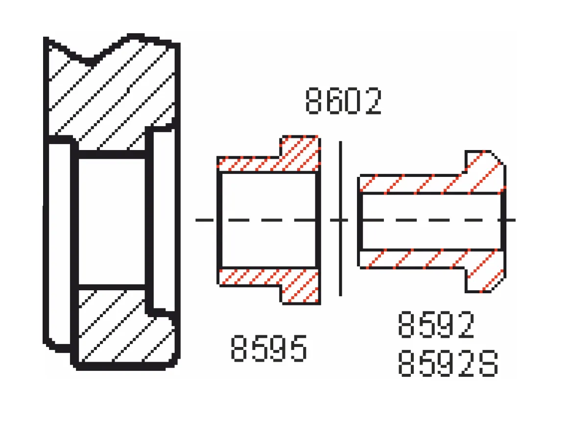
Plain 16 mm bore (Syntace X-12 V1): push the reducer bushing (8595) in from outside to the stop and tighten the dropout clamp bolt to the frame maker’s spec. Put the spacer(s) (8602) on the standard (8592) or special (8592S) bushing and push it into the reducer.
-
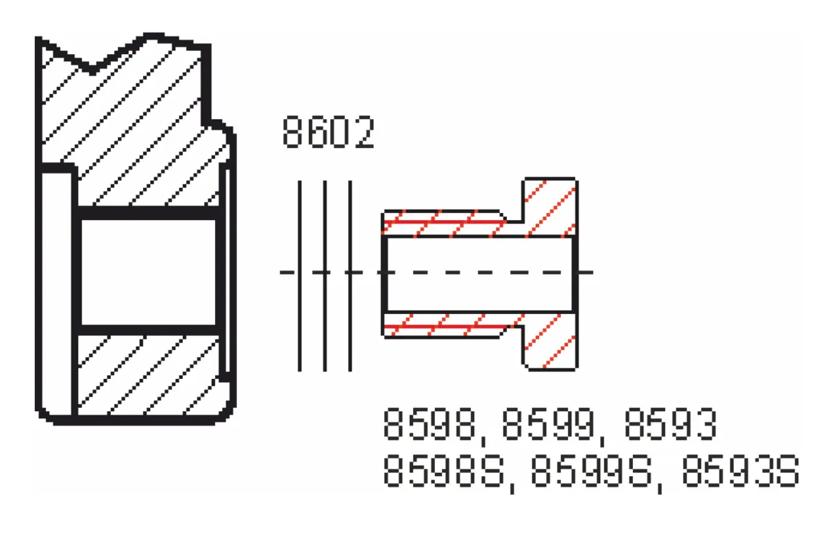
Threaded dropout (DT/Maxle, Syntace X-12 V2): put the spacer(s) on the threaded bushing — M12×1: 8598, M12×1.5: 8599, M12×1.75: 8593 (special lengths marked S) — and screw it in from outside to the stop (13 mm, 10 Nm).
-
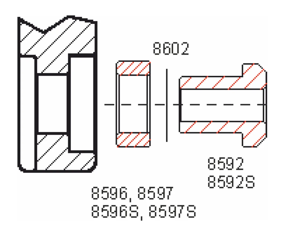
Spacer-ring system: after the spacer(s), slide the spacer ring (8596 or 8597, or a special S version) onto the bushing (8592/8592S) and push both in from outside.
-
UDH: unscrew the original UDH stud (left-hand thread), keep the original UDH washer and hanger, and screw in the Rohloff A12 UDH stud (8591, left-hand thread, 25 Nm).
4. Disc side (left, L)
Section titled “4. Disc side (left, L)”-
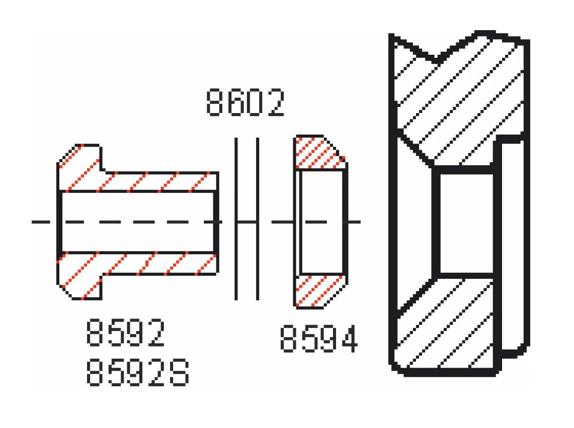
Syntace X-12 V1 and V2: spacer(s) on the bushing (8592/8592S), then the Syntace cone (8594), and both in from outside.
-
DT/Maxle: spacer(s) on the bushing, and in from outside.
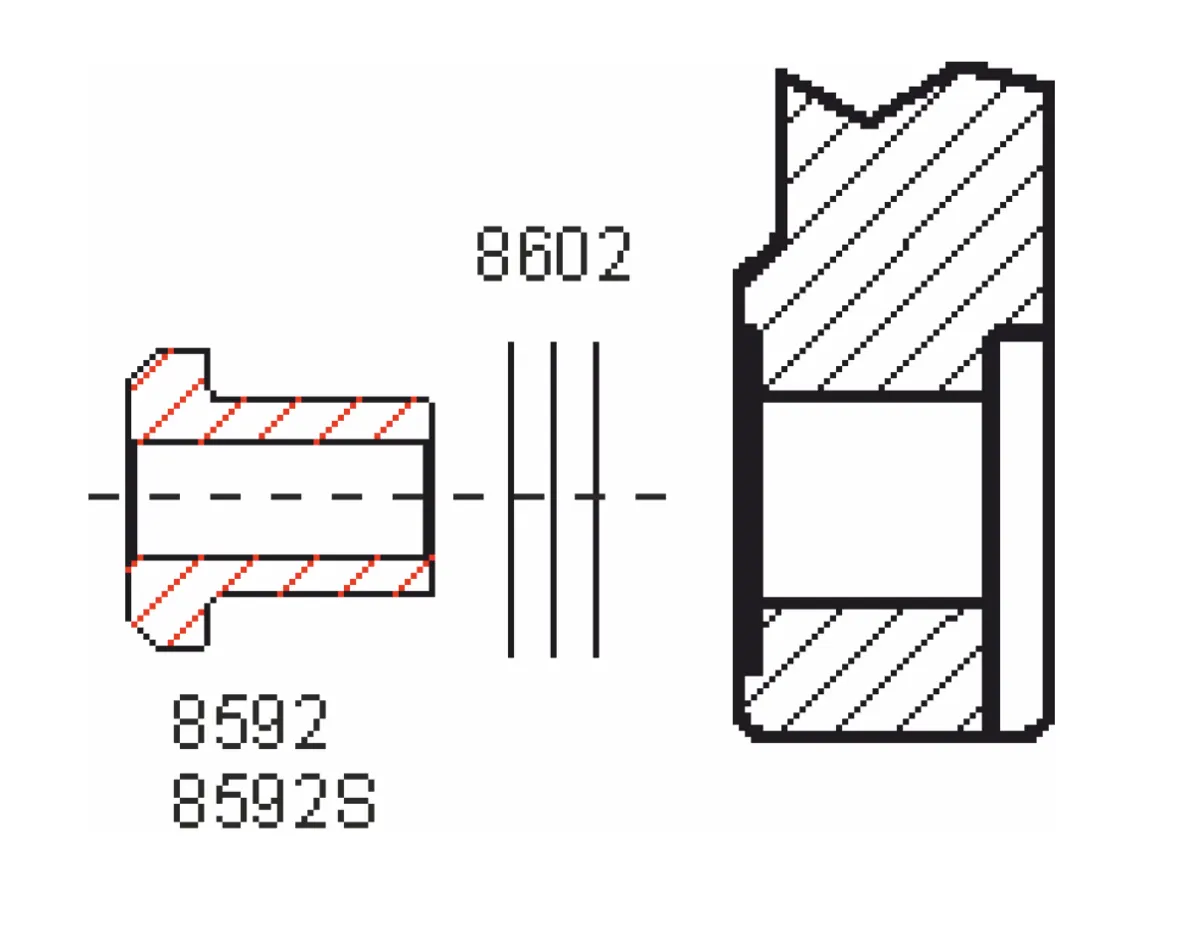
-
Spacer-ring system: spacer(s), then the spacer ring (8596/8597), and both in.
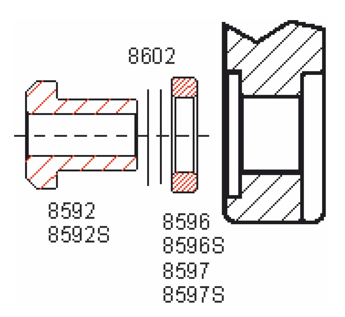
5. Bolts and Nord-Lock
Section titled “5. Bolts and Nord-Lock”-
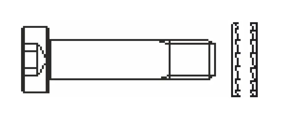
Check the Nord-Lock pairs: the teeth of the two halves face inwards, towards each other.
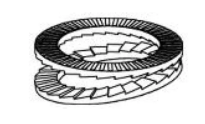
-
Put a Nord-Lock pair on each fixing bolt, push it through the bushings and screw it into the axle’s inner thread by hand — on both sides. The bolt length comes from the kit that suits the frame (8569, 8569B or 8569U, see Removing and fitting an A12 wheel).
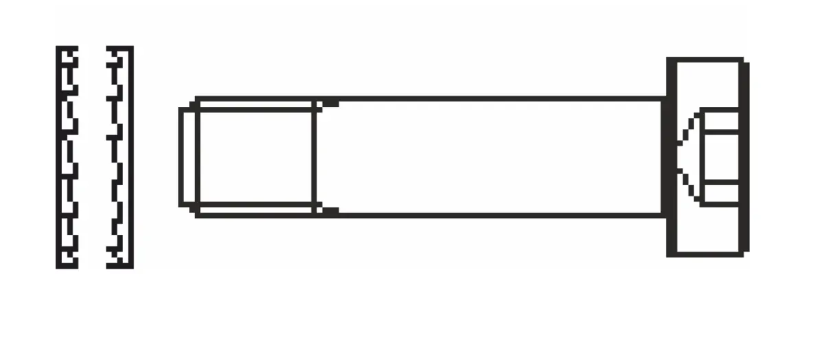
-
Tighten the two bolts alternately and in steps (5 mm Allen, 15–20 Nm).
-
The first fitting is done without chain or belt tension — now tension it to the maker’s spec and check that the wheel spins freely.
Lacing and warranty
Section titled “Lacing and warranty”To lace the wheel, clamp the hub in the truing stand with the two supplied M7 bolts (bags R and L), screwed in by hand to the stop. Official Rohloff wheel-building services have the clamping adapters. Register the warranty card with the dealer’s stamp and purchase date; the sticker on the owner’s card lists the article numbers of both sides’ A12 parts, so they can be reordered at any time.
Frequently asked questions
- Which side does the threaded A12 bushing go on?
- The sprocket side (right, R), where the dropout is threaded — as on DT/Maxle and Syntace X-12 V2. Depending on the pitch it is M12×1, M12×1.5 or M12×1.75, screwed in to the stop with a 13 mm spanner at 10 Nm. The disc side (left, L) always takes a plain bushing.